Translate

THANKS

Thanks for being touch with us on Social media and online website

×
Thanks!
for visiting the electricaldon.com website.Received many applications for ITI ELECTRICIAN for job. Kindly note our team is working on it, shortly you will receive call from them.

APPLY only if you have Electrical wiremen or Electrical Supervisor Licenses its Mandatory. !

Thankyou for your Patients. !

Search This Blog

category

Showing posts with label Q & A. Show all posts

Electrical Engineer Project

During the last century and a half, electricity has evolved from a scientific curiosity, to a luxury for wealthy people and to a daily necessity in the developed and developing world. Just as water is necessary for survival, electricity is indispensable in daily life. Without electricity, our way of life comes to a grinding halt. Modern society requires smart, simple, safe, reliable, and economical electric power infrastructure for social, political, and economic activities. The infrastructure should be efficient, flexible to expand, economical to maintain, and operate.

There are four main components of obtaining professional engineering licensure:

Education

Fundamentals of Engineering

Work Experience

Principles and Practice of Engineering 

Electrical engineering has many sub-disciplines, the most popular of which are high Voltage engineering (Power Companies), power engineering (Facilities), and power electronics. Although there are electrical engineers who focus exclusively on one of these sub-disciplines, many deals with a combination of them. Sometimes certain fields, such as electronic engineering and computer engineering, are considered separate disciplines in their own right.

Power engineering deals with the generation, transmission, and distribution of electricity as well as the design of a range of related devices. These include transformers, electric generators, and electric motors. Power engineers may work on the design and maintenance of the power grid as well as the power systems that connect to it. Such systems are called on-grid power systems and may supply the grid with additional power, draw power from the grid, or do both. Power engineers may also work on systems that do not connect to the grid, called off-grid power systems, which in some cases are preferable to on-grid systems. The future includes Satellite controlled power systems, with feedback in real-time to prevent power surges and prevent blackouts.

Electrical Engineering is the branch of engineering that deals with the technology of electricity, especially the specification and design of electrical systems and equipment for power generation and distribution, control, and communications. An electrical engineer who has a certifiable bachelor's degree in electrical engineering from a recognized School or University and satisfies the requirements for Engineer In Training (EIT) and Professional Engineer (PE) examinations and experience can apply for the state PE license. Once state registered, an Engineer by law has a primary duty to protect the public safety, health, and welfare in the facility electrical systems design by following and applying the latest building codes.

The Engineer of Record for the Electrical Systems Design is a state Registered Professional Engineer who develops the electrical system design criteria, performs the analysis and is responsible for the design, specification, preparation, and delivery of the electrical documents for the construction of projects. Projects may include private /public works, institutional, commercial facilities such as banks, office buildings, schools and colleges, hospitals, medical clinics, retail stores, parking ramps, airports, manufacturing facilities, food distribution centers, warehouses, data centers, department stores, jails, libraries, theaters, and courthouses, etc.

An Electrical System is any system and assembly of electrical components, materials, utilities, equipment, work system, machines, products, or devices which require electrical energy in order to perform their intended function.

Electrical Engineering Documents: The electrical drawings, specifications, reports, and other documents setting forth the overall design and requirements for the construction, alteration, modernization, repair, demolition, arrangement, and/or use of the electrical system, or analysis or recommendations, as prepared by the Engineer of Record for the Electrical System.

Electrical Component: An individual electrical device to be part of an electrical system.

Electrical: Any device or mechanism that operates due to the action of electricity.

Electrical Submittals: Submittals, catalog information on standard products, or drawings prepared solely to serve as a guide for fabrication and installation and requiring no engineering input.

Codes and Standards: Those nationally recognized Codes and Standards adopted directly or by reference.

To specify and design facility electrical systems including power systems, lighting, communications, alarm systems, lightning protection, grounding system and controls, an electrical engineer needs to coordinate his effort with the fellow designers: Architect, Civil Engineer, Structural Engineer, HVAC/Plumbing Engineer, Fire Protection Engineer, Voice/Data low voltage technology, Building Security, Vertical Transportation, Electric Utility, Telephone Company, and Internet Access, etc.

Power Systems Design

Power systems distribute electrical energy. Major factors to be included in the design and analysis of these systems are proper voltage levels, balances and quality, system capacity, reliability and redundancy, steady-state and transient loads, short circuit protection (design and analysis), load flow, voltage drop, harmonics, and protective device coordination. The power systems design shall meet the local building codes, the National Electrical Code (NEC), National Electrical Safety Code (NESC), and other applicable codes and standards.

Electrical engineering documents applicable to power systems shall at a minimum indicate the following:

Electrical legend

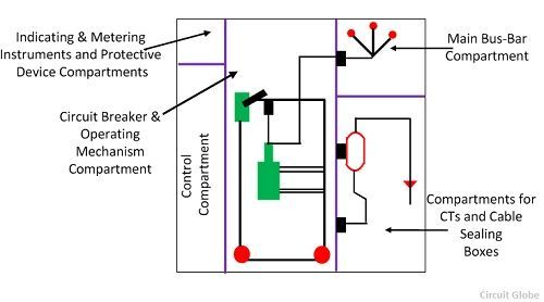
System one-line diagram or Riser Diagram

Conductor capacities (sizes) and insulation type

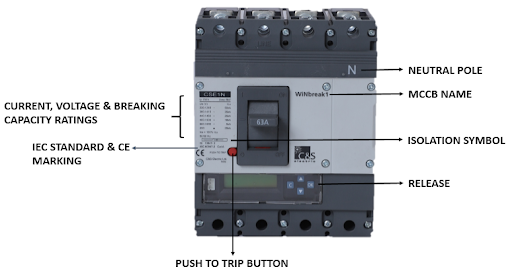
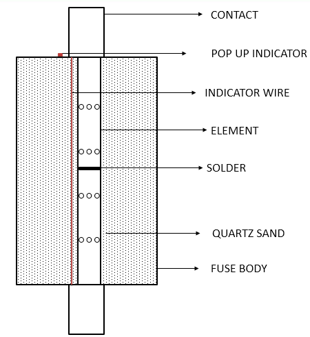
Protection devices and interrupting capability

Utility Service 

Transformer

Main and distribution panel board locations and sizes

The circuitry of all outlets and devices

Short circuit analysis

Load computations

Grounding and bonding

Low Voltage control diagrams

Schedules and details

Lighting Systems Design

Lighting systems convert electrical energy into light. Items to be included in the lighting design and analysis are average illuminance, equivalent spherical illuminance, uniformity ratios, visual comfort probability, special-purpose lighting, and the requirements of the local, state, and federal and ASHRAE 90.1 Energy Efficiency Standards, and Building Codes.

Electrical engineering documents for lighting systems shall, at a minimum, indicate the following:

Lighting fixture performance specifications and arrangements

Emergency Lighting

Exit Lighting

Lighting Control and circuiting

Communications Systems Design

Communications systems are utilized to convey messages or data. Items to be included in the design or analysis of these systems are Human factors engineering, cabling requirements, installation requirements, performance requirements, backup power requirements, the interrelationship of the various systems, and applicable regulatory requirements.

Electrical engineering documents for communications systems shall, at a minimum, indicate the following:

System riser diagram

Equipment legend

Conductor type and installation requirements

Device type and locations

Backup power sources where applicable

Alarm Systems Design

Alarm systems are used to monitor and alarm fire or other emergency condition. Items to be included in the design or analysis of these systems are structure alarm requirements, location and audibility, types of alarms and initiation devices, notification requirements, installation requirements, and backup power requirements.

Design documents for alarm systems shall, at a minimum, indicate the following:

System riser diagram

Device types and locations

Type of conductors and installation requirements including rating identification and listing requirements

Notification requirements

Backup power requirements

Lightning Protection Systems Design

Lightning Protection Systems are passive systems used to protect buildings and structures from damage caused by lightning and static discharges. Items to be considered in the design or analysis of this system include the requirements of NFPA 780.

Electrical engineering documents for lightning protection systems shall indicate:

Air terminals height and spacing

Arrangement of Main and Down conductors

Grounding points and spacing

Legend

Testing requirements of grounds

Grounding Systems Design

Grounding Systems are passive systems used to establish an electrical potential reference point in an electrical system for the proper dissipation of energy in case of abnormal or transient conditions.

Design documents for grounding systems shall indicate at a minimum the following:

type and location of grounding electrodes

bonding requirements

testing requirements

conductor material type, size, and protection requirements

separate grounding systems, properly bonded, per code and use requirements

Instrumentation And Control Systems Design

Instrumentation and control systems are used to automate processes. Items to be included in the design and analysis of these systems are reliability of control of critical processes, the safety of personnel, and suitability of instruments and control devices in the environment in which they are installed.

Electrical engineering documents for instrumentation and control systems shall indicate, at a minimum, the following:

A description of the control system functions, or a functional diagram

Specifications of control instruments and their location

Type of conductors and cables, and requirements for their installation

EMERGING ISSUES

Quality Assurance and Control of Construction Documents

Standardization, integration, and promulgation of smart grid technology, smart power distribution system, smart metering, smart peak load demand controls, smart building management systems, etc.

Building commissioning or Integrated systems testing for building electrical, HVAC, all motor equipment, and control systems.

Energy Conservation

Renewable Energy

Energy Efficiency

Emerging 3-D modeling platforms

Coordination of design documents with: Architects, Interior Designer, Lighting Design, Structural Engineering, Civil Engineering, Mechanical Engineering, Low Voltage Technology


WHAT IS IP CODE ?

 IP Code, or Ingress Protection Code[1], IEC standard 60529, sometimes interpreted as International Protection Code, classifies and rates the degree of protection provided by mechanical casings and electrical enclosures against intrusion, dust, accidental contact, and water. It is published by the International Electrotechnical Commission (IEC). The equivalent European standard is EN 60529.


LetterMeaning
ABack of hand
BFinger
CTool
DWire


LetterMeaning
HHigh voltage apparatus
MMotion during water test
SStationary during water test
WWeather conditions


NEMA enclosure[9]IP Code
1IP20
2IP22
3, 3X, 3S, 3SXIP55
3R, 3RXIP24
4, 4XIP66IP65
5IP53
6IP67
6PIP68
12, 12K, 13IP54


WHAT IS DOL starter?

DOL starters are primarily motors where a high inrush current does not cause an excessive voltage drop in the supply circuit (or where this high voltage drop is acceptable). Direct online starters are commonly used to start small water pumps, conveyor belts, fans, and compressors.

A DOL starter (or Direct On Line starter or across the line starter) is a method of starting a 3 phase induction motor. In DOL Starter an induction motor is connected directly across its 3-phase supply, and the DOL starter applies the full line voltage to the motor terminals.

WHAT IS SWITCH ?

A switch is a device that is designed to interrupt the current flow in a circuit, in other words, it can make or break an electrical circuit. ... Switches can be of mechanical or electronic type, Mechanical switches must be activated physically, by moving, pressing, releasing, or touching its contacts.


SWITCHES

What is PDB panel ?

 PDB Panels are used for Electric Power Distribution, Fault Protection, and Monitoring of different Electrical Systems. It usually consists of Incomer ACB/MCCB, Switch Fuse Unit (SFU), ELCB, MCCB, MCB, etc. Any Electrical Systems containing Inductive & Capacitive Loads consumes both Active and Reactive Power.

What is meant by MCC panel ?

 A motor control center (MCC) is an assembly to control some or all-electric motors in a central location. It consists of multiple enclosed sections having a common power bus and with each section containing a combination starter, which in turn consists of a motor starter, fuses or circuit breaker, and power disconnect.

WHAT IS SWITCHGEAR ?

 The combination of circuit or fuses, electrical disconnects switches or breakers used to isolate, protect, and control electrical equipment or gears from the defective condition are usually called switchgear.


switchgear


What Details required for Purchasing Electric Motor ?


Weight
Dimensions
Efficiency Class
Kw
Hp
Pole
Rpm
Mounting
AMP
Warranty
Efficiency
HSN
Frequency ( Hz)
Frame
Ip


What is Insulator ?

 An electrical insulator is a material in which the electron does not flow freely or the atom of the insulator has tightly bound electrons whose internal electric charges do not flow freely; very little electric current will flow through it under the influence of an electric field. This contrasts with other materials, semiconductors, and conductors, which conduct electric current more easily. The property that distinguishes an insulator is its resistivity; insulators have higher resistivity than semiconductors or conductors. The most common examples are non-metals.

A perfect insulator does not exist because even insulators contain small numbers of mobile charges (charge carriers) that can carry current. In addition, all insulators become electrically conductive when a sufficiently large voltage is applied that the electric field tears electrons away from the atoms. This is known as the breakdown voltage of an insulator. Some materials such as glass, paper, and Teflon, which have high resistivity, are very good electrical insulators. A much larger class of materials, even though they may have lower bulk resistivity, are still good enough to prevent significant current from flowing at normally used voltages, and thus are employed as insulation for electrical wiring and cables. Examples include rubber-like polymers and most plastics which can be thermoset or thermoplastic in nature.

Insulators are used in electrical equipment to support and separate electrical conductors without allowing current through themselves. An insulating material used in bulk to wrap electrical cables or other equipment is called insulation. The term insulator is also used more specifically to refer to insulating supports used to attach electric power distribution or transmission lines to utility poles and transmission towers. They support the weight of the suspended wires without allowing the current to flow through the tower to the ground.


Types of Insulator

What is Auto Transformer ?

 An Auto Transformer is a transformer with only one winding wound on a laminated core. An autotransformer is similar to a two winding transformer but differs in the way the primary and secondary winding are interrelated. A part of the winding is common to both primary and secondary sides. On load condition, a part of the load current is obtained directly from the supply and the remaining part is obtained by transformer action. An Autotransformer works as a voltage regulator.

Autotransformers can be used as a method of soft starting induction motors.

The autotransformer winding has at least three taps where electrical connections are made. Since part of the winding does "double duty", autotransformers have the advantages of often being smaller, lighter, and cheaper than typical dual-winding transformers, but the disadvantage of not providing electrical isolation between primary and secondary circuits. Other advantages of autotransformers include lower leakage reactance, lower losses, lower excitation current, and increased VA rating for a given size and mass.

Applications of Autotransformer

It is used as a starter to give up to 50 to 60% of full voltage to the stator of a squirrel cage induction motor during starting.

It is used to give a small boost to a distribution cable, to correct the voltage drop.

It is also used as a voltage regulator

Used in power transmission and distribution system and also in the audio system and railways.

what is SLD ?

Single-line diagram (SLD), also sometimes called one-line diagram, is a simplified notation for representing a three-phase power system

The one-line diagram has its largest application in power flow studies. Electrical elements such as circuit breakers, transformers, capacitors, bus bars, and conductors are shown by standardized schematic symbols. Instead of representing each of three phases with a separate line or terminal, only one conductor is represented.

It is a form of block diagram graphically depicting the paths for power flow between entities of the system. Elements on the diagram do not represent the physical size or location of the electrical equipment, but it is a common convention to organize the diagram with the same left-to-right, top-to-bottom sequence as the switchgear or other apparatus represented. A one-line diagram can also be used to show a high-level view of conduit runs for a PLC control system.

What is ELCB ?

 Earth leakage circuit breaker (ELCB) is a safety device used in electrical installations with high earth impedance to prevent shock. It detects small stray voltages on the metal enclosures of electrical equipment and interrupts the circuit if a dangerous voltage is detected. Once widely used, more recent installations instead use residual-current devices (RCDs, RCCBs, or GFCIs) which instead detect leakage current directly.

What is MCB ?

 A miniature circuit breaker (MCB) automatically switches off the electrical circuit during an abnormal condition of the network means in overload condition as well as faulty condition. Nowadays we use an MCB in a low voltage electrical network instead of a fuse. ... MCB is much more sensitive to overcurrent than a fuse

MCBs or Miniature Circuit Breakers are protective electromagnetic devices that act as a switch in a circuit. They automatically open the circuit whenever they sense the current passing over the circuit has crossed a certain limit or value. The device can also be used as a normal on and off switch manually. 

MCBs are also known as time delay tripping devices which trip and shut down the system whenever there is an overcurrent flowing for a longer period of time and there is a danger to the entire circuit. However, in the case of short-circuits, these devices can trip and stop the power supply within 2.5 milliseconds.

In an electrical system ‘Fault’ is the condition which arises due to the malfunctioning of some component or wrong electrical practice. A fault may lead to a very dangerous situation such as explosion & fire if not cleared timely, not only this, the amount of time for which fault remains in the system, it continuously deteriorates the system health causing high energy losses resulting in increased thermal stress upon the system. Faults are hazardous to the system & require to be cleared at the earliest thus, there is a need for such a device that not only is capable of clearing the fault but also has a lower opening time in order to save the let-through energy & minimize the thermal stress.

type of curve/applications the MCB is of 3 types:

B Curve: This type of MCB has a lower short circuit trip zone and can be used for Resistive/ Lighting loads, for example, lights, heaters, etc.

C Curve: These MCBs have a higher short circuit tripping zone and can be useful for the inductive type/motor loads, for ex: AC, Refrigerator, etc.

D Curve: These MCBs have a very high short circuit tripping zone and are generally used for the loads which draw a very high starting current such as Sodium Lamps. 

2 kinds of fault which disturb the system often are:

Overload: An overload is a fault condition that arises in a system when a circuit draws a higher current than its rating. For example from a 6A socket if we draw 10A current the condition is said to be overload.

Short Circuit: This is a condition in which an extremely low resistance path is created due to an accidental or intentional connection between 2 or more conductors which leads to the sudden increase of current to its peak value and voltage getting minimized to an extremely lower magnitude.

What is MCCB ?

 A moulded case circuit breaker (MCCB) is a type of electrical protection device that is used to protect the electrical circuit from excessive current, which can cause overload or short circuit.

MCCB is the device that is manufactured as an integral inner supporting an enclosed housing of insulating material. It is required for making, carrying, and breaking currents between separate contacts under normal circuit conditions and abnormal circuit conditions such as those of overload condition and short circuit conditions. MCCBs provide protection to the low-voltage distribution systems.

Quenching the arc in the air inside the moulded case, the MCCBs interrupt current with a range from few amperes to several kilo-amperes. MCCBs are useful for protecting the system against faults like Overload & Short Circuit, with the help of release which may be Thermal Magnetic or Microprocessor Type. MCCB satisfies the requirement of isolation as it provides complete isolation to the circuit. Compact Size, Lower Downtime, Reduction in inventory & Availability of various accessories makes it a distinctive product.

Specifications of MCCBs:

Ue – Rated Operational Voltage

Ui – Rated Insulation Voltage

Uimp – Impulse withstand voltage

In – Nominal Rated Current

Ics – Service Short Circuit Breaking Capacity

Icu – Ultimate Short Circuit Breaking Capacity


Components of Molded Case Circuit Breakers

Operating Mechanism: The Operating Mechanism handles the opening and shutting of the contacts. The speed that the contacts open or close is free of how quick the handle is moved. The breaker can’t be kept from stumbling by holding the handle in the on position. The handling will be in a halfway position when the contacts are stumbled.


Arc Extinguisher: An arc is made at whatever point an electrical switch interferes with a present stream. The Arc Extinguisher’s activity is to limit and separate that circular segment, subsequently stifling it. At the point when an intrusion happens and the contacts partitioned, the present course through the ionized area of the contacts actuates an attractive field around the bend and the circular segment douser.


Trip Unit: The Trip Unit is the cerebrum of the electrical switch. The capacity of the unit is to trip the working system in case of an abnormal condition. Electronic trip units are presently accessible and they can give considerably more refined insurance and observe.

The MCCB Working in itself is an incredible invention. The MCCB is a choice to wire since it needn’t bother with a substitute once an over-burden is taken note. Dissimilar to wire, this electrical switch can be just reset after a misstep and offers improved administrator security and straightforwardness without procuring working expense. For the most part, these circuits have a warm current for overcurrent and the attractive component for impeding to work quicker.

 There are several advantages of the MCCB:  

MCCBs are Compact in the measure. Hence it spares a significant space inboard plan.

MCCBs have to limit downtime. Dissimilar to in a breaker-based framework, there’s no looking for a substitution intertwine. It very well may be Reset and Switched-On again instantly in the wake of finding the blame that caused the stumbling amid activity.

MCCBs can clear a few blame previously it is expected for substitution.

MCCBs are “Upkeep Free” and its repeating costs are less.

At the point when MCCBs are utilized, at that point, there is no probability of single staging because of blame in just a single stage.

Some multi-reason adornments can be fitted with the MCCB.

MCCB with the combination of one of the two different trip elements will protect the circuit against situations such as: 

Thermal Overload:

In the conditions of overload, there is a temperature between the insulation and conductor. If the insulation remains unchecked, its life will reduce and the maintenance would be higher. It is important to catch the approach of MCCB for the better flow of circuit and lifelong approach of the product.

Short-circuit Condition:

It is the condition due to an intentional or unintentional low impedance path creation between phase wires or a neutral & phase wires, this situation leads to an excessively high current flowing through the circuit & voltage becomes negligible

Ground Fault condition:

It is also the type of short circuit which is linked with the ground phase. This is the common fault which takes place in the low voltage.

The MCCB protects the huge amount of mess and protects the system while enhancing the capability. The MCCB is highly durable and the life of these gadgets is longer than usual gadgets. It is suitable for the higher energy impact. The gadget must be installed by the professional because it is not that easy to be installed and once it is done, you are free to form the obstacles that you might face regarding electricity, short-circuits, and the low-voltage.

Nowadays MCCBs are available with 2 kinds of release, one is with thermal-magnetic &other is microprocessor release.

Thermal-magnetic uses the principle of the bimetal and electromagnetic coil. Thermal protection is required for O/L & electromagnetic or solenoid is used for S/C. but since electromagnet is a peak sensing device thus a slight transient peak can cause nuisance tripping of MCCB. This CB gives the following protections

Thermal /Overload Protection- Through Bimetal

Electromagnetic /Short Circuit Protection- Through Electromagnet

Under Voltage Protection- Through U/V Release

Microprocessor or electronic release sense true R.M.S value of current. It is simulated and calculated from peak values, which are detectable by a microprocessor. The microprocessor-based release may offer below protections which can be add on:

Earth Fault

Neutral protection

Instantaneous Over-ride

Earth Leakage

Current Unbalance

Overvoltage

Wrong Selection of MCCB:

For a few special applications, manufacturers recommend using MCCBs dedicated to that application. For Ex. For motor back up protection, there is a requirement for overload protection of the motor, it is required to match the overload settings of MCCB with that of the motor. This solution assures no damage to the motor in case of motor overloading. However, the life expectancy of contactor as per the circuit design is considered better than that of MCCB. Hence this combination will give a much lesser life, thus it can’t be suggested. Also, we can’t have single phasing protection by using MCCB. Hence, in this case, ‘Type 2’ coordination charts shall be referred to so as to make an appropriate selection.


What is RCCB ?

 Residual Current Circuit Breaker (RCCB) is an important safety measure when it comes to the protection of electrical circuits. It is a current sensing device, which can automatically measure and disconnect the circuit whenever a fault occurs in the connected circuit or the current exceeds the rated sensitivity

Principle behind RCCB

RCCB works on the principle of Kirchhoff’s law, which states that the incoming current must be equal to the outgoing current in a circuit. RCCB thus compares the difference in current values between live and neutral wires. Ideally, the current flowing to the circuit from the live wire should be the same as that flowing through the neutral wire. In case of a fault, the current from the neutral wire is reduced, the differential between the two known as Residual Current. On spotting a Residual Current, the RCCB is triggered to trip off the circuit.

A test circuit included with the Residual Current device ensures that the reliability of RCCB is tested. When the test button is pushed, the current starts to flow through the test circuit. As it creates an imbalance on the neutral coil of the device, the RCCB trips and supply is disconnected thereby checking RCCB’s reliability.

Benefits of RCCB

Provides protection against earth fault as well as any leakage current

Automatically disconnects the circuit when the rated sensitivity is exceeded

Offers the possibility of dual termination both for cable and busbar connections

Offers protection against voltage fluctuation as it includes a filtering device that guards against transient voltage levels.

 Sensitivity of RCCB

A human being is able to sustain an electric shock to the extent of 30 mA. While up to 10 mA may just evoke a prickling sensation, 10 mA onwards may lead to muscular contraction, further leading to a respiratory paralysis at around 30mA. RCCBs are therefore designed to look for small changes in residual current. In cases where protection from fire is sought, RCCBs are also used to track higher changes in residual current of up to 300mA.

Limitations of RCCB

While RCCB has many advantages, it has some limitations as well:

RCCB does not guarantee to operate if none standard waveforms are generated by loads. It’s mainly because RCCB is designed to operate on normal supply waveforms.

There might be some unwanted tripping of RCCB. It’s mainly because whenever there are sudden changes in electrical load, there can be small current flow to earth, especially in old appliances.

RCCB does not protect from current overload. It has been designed to protect only when the live current and neutral current are different. However, a current overload cannot be detected.

RCCB does not protect against line-neutral shocks. It’s mainly because the current in them is balanced. The current gets balanced as both terminals are held together.

RCCB does not protect from the overheating that strike if conductors are not properly screwed into terminals.

 Classification of RCCB

RCCB is of two types; the 2 Pole RCCB and 4 Pole RCCB.

2 Pole RCCB: This is used in case of a single-phase supply connection that has only a live and a neutral wire.

4 Pole RCCB: This is used in case of a three-phase supply connection.

Rating from 10 Amp ….100 Amp

Sensitivity 30,100,300 m Amp

RCCB is therefore extremely important in providing real-time protection for circuits. In industries and high voltage commercial setups especially, its importance cannot be undermined as there is always a risk of shocks and accidental deaths on account of it. At C&S Electric, we offer Wintrip RCCB, a state-of-the-art product fit for industrial, residential, and commercial applications. C&S RCCBs conforms to IEC 61008 – 1 and is used for both control and isolation of electrical circuits. Being a respected global brand for power management products for over 50 years, with C&S Electric you can rest assured knowing that you are in safe hands.


What is Circuit Breaker ?

 A circuit breaker is a switching device which also offers protection against short circuit. Unlike a fuse, the circuit breaker does not blow off but trips whenever there is a fault. The circuit breaker complies with IEC 60947-2 & can offer protection up to 150KA even beyond that, also a circuit breaker can offer a no of protections such as against:

Overload

Short Circuit

Under Voltage

Neutral

Earth Fault


Siemens and L&t Miniature Circuit Breaker, Rs 93 /piece Mehta Enterprise |  ID: 2068278533


ABB Moulded Case Circuit Breakers, P. C. Customer Service Centre | ID:  19754258162

Buy Siemens 3WT8101 6UA34 5AB2 - ACB 3WT Withdrawable design with Guide  Frame EDO Online at Best Prices in India

A circuit breaker is not required to be replaced after tripping once, instead it must complete its total no of operations as declared by the manufacturer. The tripping time for the circuit breaker may vary w.r.t its type, for example. the trip time for MCCB is less than 10ms & the opening time for ACB shall be less than 30ms. Not only this, but MCCB also has a dedicated position for tripping, whenever the MCCB trips, but its actuator lever also comes in between i.e. neither in ‘ON’ nor in ‘OFF’ position.

According to the medium of arc quenching, the circuit breaker can be differentiated as below


SNO

MEDIUM OF ARC QUENCHING

CIRCUIT BREAKER

1

AIR

ACB, MCCB

2

VACUUM

Vacuum Circuit Breaker

3

GAS

SF6 Circuit Breaker

4

OIL

Oil Circuit Breaker


method of tripping, the circuit breaker can be below types


SNO

METHOD OF TRIPPING

CIRCUIT BREAKER

1

BIMETAL (for Overload) &

Armature (for Short Circuit)

Thermal Magnetic Type

2

ELECTRONIC

Microprocessor Type


What is Fuse ?

Fuse is a device that blows in case of a fault & can offer protection up to 80KA even beyond that. Whenever there is a fault in the system the fuse blows off & protects the system by cutting off the supply. A fuse is generally made of a ceramic body, having an element, The body is filled with quartz sand as shown in the fig:


Whenever there is an overload in the system, the solder as shown gets into a chemical reaction resulting in cutting off the supply. In the case of a short circuit, the element gets torn due to the application of high electrodynamic force on the same because of high current such as a short circuit. The blown fuse can be easily identified by the pop up indicator which pops up whenever the fuse interrupts. The function of quartz sand is to successfully quench the arc & absorb the pressure thus, not letting the fuse to explode. The fuse is the staunchest combatant of the system as it is the quickest interrupting device available in the entire electrical system. The fuse blown within 2-5ms hence saving the maximum amount of let-through energy.

Fuse can be identified as mentioned below:

The first letter is ‘a’ if the fuse is for short-circuit protection only; an associated device must provide overload protection.

The first letter is ‘g’ if the fuse is intended to operate even with currents as low as those that cause it to blow in one hour, ex. Overload. These are considered general-purpose fuses for the protection of wires.

The second letter indicates the type of equipment or system to be protected:

G – General purpose protection of wires and cables

M – Motors

PV – Solar photovoltaic arrays as per 60269-6

R, S – Rectifiers or semiconductors as per 60269-5

Tr – Transformers

Fuse although, is the most dependable & trusted protection device but can be used only one time, in no case the fuse can be repaired after it blows off it only needs to be replaced.


What is Transformer Vector Groups ?

 The transformer vector group shows the phase difference between the primary and secondary sides of the transformer. It also determines the high voltage and low voltage windings arrangement of three-phase transformers. The three-phase transformer is connected in various ways. On the basis of connection, the vector group of the transformer is determined.

A three-phase transformer is divided into four main groups according to the phase difference between the corresponding line voltage on the high voltage side and the low voltage sides. The phase difference is the angle by which the low voltage line lags the high line voltage, and is measured in units of 30° in a clockwise direction. These groups are

Group number 1 – no phase displacement

Group number 2 – 180° phase displacement.

Group number 3 – (-30°) phase displacement.

Group number 4 – (+ 30°) phase displacement.

The connection Y d 11 gives the following information – Y indicates that the high voltage is connected to star and d indicates the low voltage is connected in delta. The 11 indicates that the low line voltage lag, high line voltage by 11 Χ 30° = 330° measured from higher voltage phasor in a clockwise direction.

The phasor differences can also be measured by using the clock methods. Consider the minute hand of the clock shown the high voltage and the low voltage winding is represented by the hour hand. The angle of 30° is the angle between two adjacent figures on the clock dial and is taken as the unit of dial shift.


Vector Group of 3-phase Transformer | Electrical Concepts


When the hour hand of the clock is at 12, then the phase displacement is zero. When the hour hand is at 1 then the phase shift -30° degree. At 6 the phase shift is 6 Χ 30º = 180º. Similarly, when the hour hand is at 11 the phase shift is 11 Χ 30º  = 330º.


The number 0, 6, 1, and 11 in the group reference number indicates the primary to secondary phase shift regarding the hours of the clock. The connection designated by D y 11 is the delta-star transformer in which the low voltage line phasor is at 11 and is a phase advanced of +30° on the corresponding line voltage on the high voltage side.


Note: The only transformer in the same group may be connected in parallel. For example, a star-star, 3-phase transformers can be parallel with another three-phase transformer whose windings are either connected in Y-Y or ∆-∆. The ∆-∆ transformer cannot be parallel with Y-∆ transformer.


What is outdoor substation ?

substation which is used for all voltage levels between 55 KV to 765 KV is called outdoor substation. ... The outdoor substations are mainly classified into two types, namely pole-mounted substation and foundation-mounted substations.


Pole Mounted Substation

Foundation Mounted Substation


What is indoor substation ?

 substation in which the apparatus is equipped inside the substation building is called indoor substation.

indoor substation is subdivided into several compartments like control compartment, indicating and metering instruments and protective device compartment main bus-bar compartment, current transformer and cable sealing box compartment as shown in the figure below.


indoor-substations


Transformer Fittings And Accessories

  Oil conservator with drain plug and oil filling hole Oil level indicator Drain valve with plug Filter valve with plug Air release vent Exp...