VOLTAGE |
66KV |
132KV |
220KV |
400KV |
| 66KV | 2.4 Mtr | 3 Mtr | 4.5 Mtr | 5.4 Mtr |
| 132KV | 3 Mtr | 3 Mtr | 4.5 Mtr | 5.4 Mtr |
| 220KV | 4.5 Mtr | 4.5 Mtr | 4.5 Mtr | 5.4 Mtr |
| 440KV | 4.5 Mtr | 5.4 Mtr | 5.4 Mtr | 5.4 Mtr |

Electrical cloud of answers, Unlimited study Notes, and Downloads with videos
Showing posts with label Electrical. Show all posts
Showing posts with label Electrical. Show all posts
Minimum Clearances between Lines crossing each other
ELECTRICAL GLOSSARY
Top Tooltip
Move the mouse over the text below:
AC adapter
An external power supply for portable devices that allows them to operate from wall-socket electricity.
AC power plugs and sockets
Electrical connectors used with alternating current.
AC power
Electric power where the current reverses direction periodically.
AC/AC converter
A power converter where the input and output are both alternating currents but may differ in frequency or other characteristics.
AC/DC receiver design
A radio receiver that can operate from either alternating current or direct current wall socket power.
AC/DC conversion
A radio receiver that can operate from either alternating current or direct current wall socket power.
AC/DC conversion
Rectification of AC current, so that current flows in only one direction.
Active rectification
A circuit where rectifier devices are externally controlled to change AC to a current flowing in one direction.
AC
An electric current that reverses its direction many times a second at regular intervals..
Ammeter
An instrument for measuring the flow of electrical current in amperes. Ammeters are always connected in series with the circuit to be tested.
Ah
Ampere-hour(s): A measure of battery capacity. A 4Ah battery could, for instance, deliver 1A for 4 hours, 1/2A for 8 hours, etc..
Armature
The movable part of a generator or motor. It is made up of conductors which rotate through a magnetic field to provide voltage or force by electromagnetic induction. The pivoted points in generator regulators are also called armatures.
AFCI
A breaker that shuts off current in a circuit instantly when an arc fault is detected.
Alternator
electromechanical device that converts mechanical power into AC electrical power.
Typically, a magnet spins inside a coil, inducing alternating current in the windings. The magnet can be a permanent magnet, an iron rotor in which a magnetic field is induced, or an electromagnet powered by an externally applied current.
Ambient Temperature
Temperature of the air surrounding a component.
Amp
Ampere
Ampacity
The amount of current a conductor can carry without exceeding its specified temperature, in amperes.
Ampere
Ampere(s), the unit of electrical current. Current is defined as the amount of charge that flows past a give point, per unit of time.
The symbol I is used for current in equations and A is the abbreviation for ampere.
Ampere-hour
A measure of charge (or current flow over time).One ampere-hour (or amp-hour or Ah) is a current of one ampere flowing for one hour. The amount of charge transferred in that hour is 3,600 coulombs (ampere-seconds).
A milliampere-hour (mAh or milliamp-hour) is a thousandth of an amp-hour.
An ampere-second (A-s or amp-second) is an amp supplied for one second.
AMR
Automatic Meter Reading: A system installed to read a utility meter remotely.
ANSI
American National Standards Institute
APC
Automatic Power Control
ATE
Automatic test equipment
GLOSSARY
DEFINATION
Autotransformer
An autotransformer is a transformer that uses a common winding for both the primary and secondary windings. Essentially an inductor with a center-tap, an autotransformer is often used in power-supply boost-converter applications to achieve a higher output voltage, while limiting the peak flyback voltage seen by the power switch.
Buck
A "buck" or "step-down" switch-mode voltage regulator is one in which the output voltage is lower than its input voltage
Capacitor
A capacitor is a passive electronic component that consists of two conductive plates separated by an insulating dielectric. A voltage applied to the plates develops an electric field across the dielectric and causes the plates to accumulate a charge. When the voltage source is removed, the field and the charge remain until discharged, storing energy.
Capacitance (or C, measured in farads), dictates the amount of charge that can be stored at a given voltage (a one-farad capacitor charged to one volt will hold one Coulomb of charge).
Circuit
A closed path in which electrons from a voltage or current source flow. Circuits can be in series, parallel, or in any combination of the two.
Circuit Breaker
An automatic device for stopping the flow of current in an electric circuit. To restore service, the circuit breaker must be reset (closed) after correcting the cause of the overload or failure. Circuit breakers are used in conjunction with protective relays to protect circuits from faults.
Conductor
Any material where electric current can flow freely. Conductive materials, such as metals, have a relatively low resistance. Copper and aluminum wire are the most common conductors.
Corona
The flow of an electric charge through a conductor. An electric current can be compared to the flow of water in a pipe. Measured in amperes.
Cycle
The change in an alternating electrical sine wave from zero to a positive peak to zero to a negative peak and back to zero. See Frequency.
Demand
The average value of power or related quantity over a specified period of time.
DC
Direct Current (DC) — An electric current that flows in only one direction.
Distortion
In systems that handle electrical signals, distortion is a generally unwanted change in the signal.
Not all signal alterations are considered distortion. For instance, a uniform delay or a linear attenuation or amplification would generally not be considered distortion.
DVM
Digital voltmeter
DMM
Digital Multimeter: Measuring instrument or VOM (e.g. voltage, resistance, current) with a digital display.
DP
Differential phase
DPD
Digital phase detector
DPDT
Double-pole/double-throw
DPM
Digital panel meter
DPST
Double-pole/single-throw
Dual Phase Controller
Switching regulator that employs dual-phase technique to reduce output noise and boost output current capability.
Feeder
The conductors that feed panels other than the service panel.
Frequency
The number of cycles per second. Measured in Hertz. If a current completes one cycle per second, then the frequency is 1 Hz; 60 cycles per second equals 60 Hz.
Fuse
A circuit interrupting device consisting of a strip of wire that melts and breaks an electric circuit if the current exceeds a safe level. To restore service, the fuse must be replaced using a similar fuse with the same size and rating after correcting the cause of failure.
Ground Fault
The leaking of current to the grounding conductor.
Generator
A device which converts mechanical energy into electrical energy.
Ground
The reference point in an electrical circuit from which voltages are measured, a common return path for electric current, or a direct physical connection to the Earth.
GFCI
Ground Fault Circuit Interrupters (GFCI) — A device intended for the protection of personnel that functions to de-energize a circuit or portion thereof within an established period of time when a current to ground exceeds some predetermined value that is less than that required to operate the overcurrent protective device of the supply circuit.
HVAC
Heating, Ventilation, and Air Conditioning: Industry term for the systems and technology responsible for the heating, ventilation, and air conditioning in buildings. HVAC systems regulate comfort (temperature and humidity), energy efficiency, and air quality.
Hz
Hertz: A measure of frequency. An older term is cycles per second, or cps.
Inductance
The property of a conductor by which a change in current flowing through it induces (creates) a voltage (electromotive force) in both the conductor itself (self-inductance) and in any nearby conductors (mutual inductance). Measured in henry (H).
Insulator
Any material where electric current does not flow freely. Insulative materials, such as glass, rubber, air, and many plastics have a relatively high resistance. Insulators protect equipment and life from electric shock.
Inverter
An apparatus that converts direct current into alternating current.
I/O
Input/output
Impedance
Impedance, represented by the symbol Z, is a measure of the opposition to electrical flow. It is measured in ohms.
For DC systems, impedance and resistance are the same, defined as the voltage across an element divided by the current (R = V/I).
Inrush Current
A momentary input current surge, measured during the initial turn-on of the power supply. This current reduces to a lower steady-state current once the input capacitors charge. Hotswap controllers or other forms of protection are often used to limit inrush current, because uncontrolled inrush can damage components, lower the available supply voltage to other circuits, and cause system errors.
Lm
Lumen(s)
Load
Anything which consumes electrical energy, such as lights, transformers, heaters and electric motors.
Open Circuit
An open or open circuit occurs when a circuit is broken, such as by a broken wire or open switch, interrupting the flow of current through the circuit. It is analogous to a closed valve in a water system.
Lm/W
Lumen(s) per watt
LOP
Loss of power
LOS
Loss of signal
LV
Low Voltage
HV
High Voltage
NC
Normally closed (switch contacts)
NO
Normally open (Switch contact)
OC
Overcurrent
Overvoltage Protection
Overvoltage Protector (OVP) refers to a circuit that protects downstream circuitry from damage due to excessive voltage. An OVP monitors the DC voltage coming from an external power source, such as an off-line power supply or a battery, and protects the rest of the connected circuitry using one of two methods: a crowbar clamp circuit or a series-connected switch.
The crowbar short-circuits or clamps the supply line to limit the voltage, possibly triggering other forms of protection such as a fuse.
Parallel Circuit
A circuit in which there are multiple paths for electricity to flow. Each load connected in a separate path receives the full circuit voltage, and the total circuit current is equal to the sum of the individual branch currents.
Polarity
A collective term applied to the positive (+) and negative ( - ) ends of a magnet or electrical mechanism such as a coil or battery.
Power
The rate at which electrical energy is transferred by an electric circuit. Measured in Watts.
Power Factor
The ratio of the actual electrical power dissipated by an AC circuit to the product of the r.m.s. values of current and voltage. The difference between the two is caused by reactance in the circuit and represents power that does no useful work.
Protective Relay
A relay device designed to trip a circuit breaker when a fault is detected.
Rectifier
An electrical device that converts an alternating current into a direct one by allowing a current to flow through it in one direction only.
Rotor
The rotating part of an electrical machine such as a generator, motor, or alternator.
Relay
A relay is an electromagnetic switching device consisting of an armature which is moved by an electromagnet to operate one or more switch contacts.
Some advantages of relays are that they provide amplification and isolation and are straightforward. They can switch difficult voltages (e.g. RF or high-powered AC) with complete isolation and no worries about level translation.
Resistance
Resistance, represented by the symbol R and measured in ohms, is a measure of the opposition to electrical flow in DC systems. Resistance is the voltage across an element divided by the current (R = V/I).
RMS
Root mean square
RTD
Resistance Temperature Detector (RTD) is a device with a significant temperature coefficient (that is, its resistance varies with temperature). It is used as a temperature measurement device, usually by passing a low-level current through it and measuring the voltage drop. A thermistor is a common type of RTD.
Series Circuit
A circuit in which there is only one path for electricity to flow. All of the current in the circuit must flow through all of the loads.
Series-Parallel Circuit
A circuit in which some of the circuit components are connected in series and others are connected in parallel.
Service
The conductors and equipment used to deliver energy from the electrical supply system to the system being served.
Short Circuit
When one part of an electric circuit comes in contact with another part of the same circuit, diverting the flow of current from its desired path.
Lug
Used to terminate a wire.
Neutral
the return conductor in a circuit. It usually has white insulation. More properly called the grounded conductor because it returns current to ground at the service panel. Note that this is different from the green-sheathed or bare copper grounding conductor that does not carry current except in case of equipment fault.
Overload
equipment or wire runs in excess limit of its normal full-load rating
S/S
Single supply
SPDT
Single-pole/double-throw switch
SPST
Single-pole/single-throw switch
TDR
Time-delay relay
Transformer
An inductive electrical device for changing the voltage of alternating current.
A transformer consists of two magnetically coupled coils. Alternating current in one (called the "primary") creates a changing magnetic field which induces a current in the second coil (the "secondary"). A core made of iron or ferrite generally connects the two coils, but higher frequency devices can work without a ferrous core.
Transformers have two primary functions: Voltage transformation and isolation:
The voltage of the secondary can be higher or lower than the voltage that drives the primary and is determined by the ratio of turns of wire in the two coils.
Isolation refers to the fact that the coils are connected only by a magnetic field, so they can be independent of a common ground.
Primary applications are for power and for signal isolation / impedance transformation.
An autotransformer is a transformer with a single coil with intermediate "taps' to effect the change outgoing voltages. They do not provide isolation.
Transformer capacity is rated in kilovolt-amps (KVA): The volts x amps / 1000.
Uninterruptible Power Supply
An uninterruptible power supply (UPS) is a device that maintains power in the event of a failure. A UPS commonly includes a battery that is kept charged and ready. When power fails, the battery supplies power, as long as it lasts. When the battery fails, a UPS may contain circuitry that triggers an orderly shutdown.
An uninterruptible power supply may also provide line regulation, protecting against voltage variations.
VRMS
VRMS stands for root-mean-square voltage.
POWER
Electric power definition
The electric power P is equal to the energy consumption E divided by the consumption time t:

P is the electric power in watt (W).
E is the energy consumption in joule (J).
t is the time in seconds (s).
Example
Find the electric power of an electrical circuit that consumes 120 joules for 20 seconds.
Solution:
E = 120J
t = 20s
P = E / t = 120J / 20s = 6W
Electric power calculation
P = V ⋅ I
or
P = I 2 ⋅ R
or
P = V 2 / R
P is the electric power in watt (W).
V is the voltage in volts (V).
I is the current in amps (A).
R is the resistance in ohms (Ω).
Power of AC circuits
The formulas are for single-phase AC power.
For 3 phase AC power:
When line to line voltage (VL-L) is used in the formula, multiply the single phase power by square root of 3 (√3=1.73).
When the line to zero voltage (VL-0) is used in the formula, multiply the single-phase power by 3.
Real power
Real or true power is the power that is used to do the work on the load.
P = Vrms Irms cos φ
P is the real power in watts [W]
Vrms is the rms voltage = Vpeak/√2 in Volts [V]
Irms is the rms current = Ipeak/√2 in Amperes [A]
φ is the impedance phase angle = phase difference between voltage and current.
Reactive power
Reactive power is the power that is wasted and not used to do work on the load.
Q = Vrms Irms sin φ
Q is the reactive power in volt-ampere-reactive [VAR]
Vrms is the rms voltage = Vpeak/√2 in Volts [V]
Irms is the rms current = Ipeak/√2 in Amperes [A]
φ is the impedance phase angle = phase difference between voltage and current.
Apparent power
The apparent power is the power that is supplied to the circuit.
S = Vrms Irms
S is the apparent power in Volt-amper [VA]
Vrms is the rms voltage = Vpeak/√2 in Volts [V]
Irms is the rms current = Ipeak/√2 in Amperes [A]


Real / reactive / apparent powers relation
The real power P and reactive power Q give together the apparent power S:
P2 + Q2 = S2

P is the real power in watts [W]
Q is the reactive power in volt-ampere-reactive [VAR]
S is the apparent power in Volt-amper [VA]


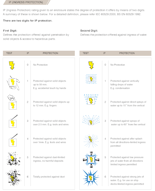
WHAT IS IP CODE ?
IP Code, or Ingress Protection Code[1], IEC standard 60529, sometimes interpreted as International Protection Code, classifies and rates the degree of protection provided by mechanical casings and electrical enclosures against intrusion, dust, accidental contact, and water. It is published by the International Electrotechnical Commission (IEC). The equivalent European standard is EN 60529.
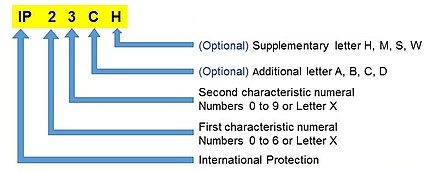
| Letter | Meaning |
|---|---|
| A | Back of hand |
| B | Finger |
| C | Tool |
| D | Wire |
| Letter | Meaning |
|---|---|
| H | High voltage apparatus |
| M | Motion during water test |
| S | Stationary during water test |
| W | Weather conditions |
| NEMA enclosure[9] | IP Code |
|---|---|
| 1 | IP20 |
| 2 | IP22 |
| 3, 3X, 3S, 3SX | IP55 |
| 3R, 3RX | IP24 |
| 4, 4X | IP66, IP65 |
| 5 | IP53 |
| 6 | IP67 |
| 6P | IP68 |
| 12, 12K, 13 | IP54 |


INDUSTRIAL SWITCHES
Rotary Cam Switch
Isolator Switches
Changeover Switches
Multistep Switches
Instrumentation Selector Switches
Motor Control Switches
Control Switches
Breaker Control Switch
L.T.Control Switch
Micro Switch
Led Indicating Lamps
Toggle Switch
Rotary Switch
Current Transformers
CHANGEOVER SWITCH
A changeover switch is designed to transfer a house (or business) electricity from the commercial power grid to a local generator when n outage occurs. Also known as “transfer switches,” they connect directly to the generator, commercial power supply or line, and the house.
The automatic changeover is installed where the main supply is of three-phase but the generator is either single-phase or three-phase. ... Automatic changeover shifts to the generator load automatically after the absence of all three phases of mains and when the generator is started.
Install a Changeover switch (about 63-100A depends on the load) near the main distribution board in the home. Connect the main power supply (Line and Neutral) as in coming to the first upper slots of Changeover Switch as shown in fig. Connect a 6 AWG (7/064″ or 16mm2)” cable wire to the lower two slots of the Changeover switch.
Changeover Switch. Automatic Transfer Switch. Onload Changeover Switches. Bypass Switch. Double Power Automatic Transfer Switches. Low Voltage Transfer Switches. Low Voltage Switches.
Changeover switch finds wide applications in industries as well as in domestic areas especially in Individual Bungalow(IB) for use in low voltage distribution circuits. Changeover switches are used to shift from one source of supply to another source and vice versa. The changeover switch comes in 2P and 4P versions, for single and three-phase applications respectively. It has three positions ( I-O-II) with center-off. They are switch disconnectors with independent manual operation, capable of making, carrying, and breaking currents under normal circuit conditions


Subscribe to:
Posts (Atom)
-
A Static Transfer Switch (STS) utilizes a static electronic component (SCR), which permits a transfer in less than four milliseconds (1/4 o...
-
WTI and OTI of Transformer The WTI means winding temperature Indicator and OTI means Oil Temperature Indicator which indicates the win...
-
 IP Code, or Ingress Protection Code[1], IEC standard 60529, sometimes interpreted as International Protection Code, classifies and rates th...
 -
Open circuit test or No-load Test of Transformer The Open circuit test of the transformer is one of the type test of transformer by which ...
-
Low voltage measurement and control device is mainly used for the measurement and control of 0.4KV voltage grade of low voltage wire feedi...
-
Elements - RESISTOR - CAPACITANCE OR CAPACITOR - INDUCTOR = reactance = impedance =susceptance =admittance - VOLTAGE SOURCE - CURRENT...
-
Earthing or Neutral Grounding Transformer When a transformer is used for the purpose of providing a neutral point for grounding purpose in...
-
auto-put-into device of reserve-source device is divided into the incoming line and the busbar connection,The device can be used in the 11...
-
Differential protection schemes transformer protection schemes motor protection relay line protection relay generator protection device


