Translate

THANKS

Thanks for being touch with us on Social media and online website

×
Thanks!
for visiting the electricaldon.com website.Received many applications for ITI ELECTRICIAN for job. Kindly note our team is working on it, shortly you will receive call from them.

APPLY only if you have Electrical wiremen or Electrical Supervisor Licenses its Mandatory. !

Thankyou for your Patients. !

Search This Blog

Difference Between Voltage & Current


Comparison Chart

Basis for ComparisonVoltageCurrent
DefinitionDifference between two points of an electric fieldThe flow of charges between two points
UnitVoltAmpere
SymbolVI
Formulavotlage-equationcurrent-equation
Field CreatedMagnetic FieldElectrostatic Field
TypesAlternating voltage & Direct voltageAlternating Current and Direct Current
PolarityAlternating voltage changes, but the direct voltage can not change its polarity.Alternating current changes its polarity but the polarity of the direct current remains constant.
ProducesAlternatorVoltage
Measuring instrumentVoltmeterAmmeter
Charges1 Volt = 1 Joule/ Coulomb1 Amperes = 1 coulomb /second
Series ConnectionUnequal in all the componentsEqually distributed in all the component
Parallel ConnectionThe magnitude of voltage remains same in all the componentThe magnitude of current vary in all the components.
LossDue to impedanceDue to passive elements
RelationIt is the cause of the currentIt is the effect of the voltage

Difference Between Current Transformer (CT) & Potential Transformer (PT)

Comparison Chart

Basis for ComparisonCurrent TransformerPotential Transformer
DefinitionTransform the current from high value to low value.Transform the voltage from high value to the low value.
Circuit Symbolcurrent-transformer-circuit-diagram-1potential-transfomer-circuit-diagram
CoreUsually built up with lamination of silicon steel.It is made up of with high-quality steel operating at low flux densities
Primary WindingIt carries the current which is to be measuredIt carries the voltage which is to be measured.
Secondary WindingIt is connected to the current winding of the instrument.It is connected to the meter or instrument.
ConnectionConnected in series with the instrumentConnected in parallel with the instrument.
Primary CircuitHas a small number of turnsHas a large number of turns
Secondary CircuitHas a large number of turns and cannot be an open circuit.Has a small number of turns and can be an open circuit.
Range5A or 1A110v
Transformation RatioHighLow
BurdenDoes not depends on the secondary burdenDepends on the secondary burden
InputConstant currentConstant Voltage
Full line currentThe primary winding consists of the full line current.The primary winding consists of the full line voltage.
TypesTwo types ( Wound and Closed Core )Two types (Electromagnetic and Capacitor voltage)
ImpedanceLowHigh
ApplicationsMeasuring current and power, monitoring the power grid operation, for operating protective relay,Measurement, power source, operating protective relay,

Potential Transformer (PT)

 The potential transformer may be defined as an instrument transformer used for the transformation of voltage from a higher value to a lower value. This transformer step down the voltage to a safe limit value which can be easily measured by the ordinary low voltage instrument like a voltmeter, wattmeter and watt-hour meters, etc.


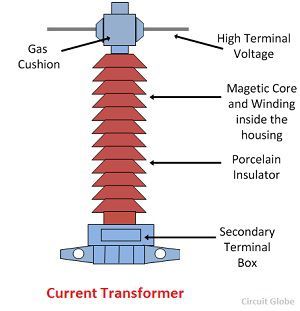
Construction of Potential Transformer

The potential transformer is made with high-quality core operating at low flux density so that the magnetizing current is small. The terminal of the transformer should be designed so that the variation of the voltage ratio with load is minimum and the phase shift between the input and output voltage is also minimum.


The primary winding has a large number of turns, and the secondary winding has a much small number of turns. For reducing the leakage reactance, the co-axial winding is used in the potential transformer. The insulation cost is also reduced by dividing the primary winding into the sections which reduced the insulation between the layers.


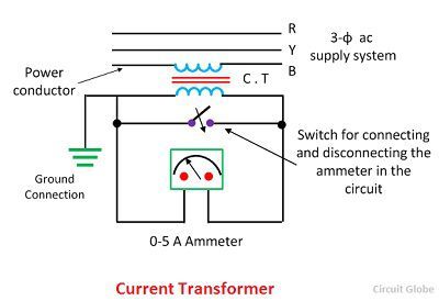
Connection of Potential Transformer

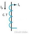
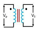
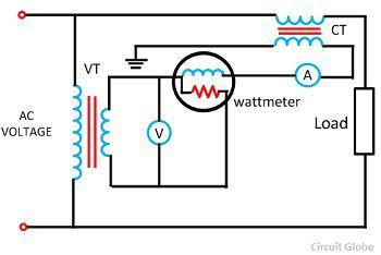
The potential transformer is connected in parallel with the circuit. The primary windings of the potential transformer are directly connected to the power circuit whose voltage is to be measured. The secondary terminals of the potential transformer are connected to the measuring instrument like the voltmeter, wattmeter, etc. The secondary windings of the potential transformer are magnetically coupled through the magnetic circuit of the primary windings.


potential-transformer


The primary terminal of the transformer is rated for 400V to several thousand volts, and the second terminal is always rated for 400V. The ratio of the primary voltage to the secondary voltage is termed as transformation ratio or turn ratio.


Types of Potential Transformer

The potential transformer is mainly classified into two types, i.e., the conventional wound types (electromagnetic types) and the capacitor voltage potential transformers.


Conventional wound type transformer is very expensive because of the requirement of the insulations. The capacitor potential transformer is a combination of a capacitor potential divider and a magnetic potential transformer of a relatively small ratio.


The circuit diagram of the capacitor potential transformer is shown in the figure below. The stack of high voltage capacitors from the potential divider, the capacitors of two sections become C1 and C2, and the Z is the burden.


capacitor-potential-transformer-circuit-diagram

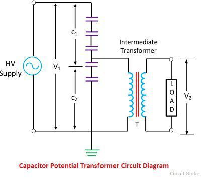
The voltage applied to the primary of the intermediate transformer is usually of the order 10kV. Both the potential divider and the intermediate transformer have the ratio and insulation requirements which are suitable for economical construction.


The intermediate transformer must be of very small ratio error, and phase angle gives the satisfactory performance of the complete unit. The secondary terminal voltage is given by the formula shown below.


capacitor-transformer


Ratio and Phase Angle Errors of Potential Transformer

In an ideal potential transformer, the primary and the secondary voltage is exactly proportional to the primary voltage and exactly in phase opposition. But this cannot be achieved practically due to the primary and secondary voltage drops. Thus, both the primary and secondary voltage is introduced in the system.


Voltage Ratio Error – The voltage ratio error is expressed in regarding measured voltage, and it is given by the formula as shown below.


ratio-current-transformer-equation


Where Kn is the nominal ratio, i.e., the ratio of the rated primary voltage and the rated secondary voltage.


Phase Angle Error – The phase angle error is the error between the secondary terminal voltage which is exactly in phase opposition with the primary terminal voltage.


The increases in the number of instruments in the relay connected to the secondary of the potential transformer will increase the errors in the potential transformers.


The burden of a Potential Transformer

The burden is the total external volt-amp load on the secondary at the rated secondary voltage. The rated burden of a PT is a VA burden which must not be exceeded if the transformer is to operate with its rated accuracy. The rated burden is indicated on the nameplate.


The limiting or maximum burden is the greatest VA load at which the potential transformer will operate continuously without overheating its windings beyond the permissible limits. This burden is several times greater than the rated burden.


Phasor Diagram of a Potential Transformer

The phasor diagram of the potential transformer is shown in the figure below.


potential-transformer-phasor-diagram


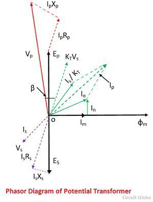
Where, Is – secondary current

Es – secondary induced emf

Vs – secondary terminal voltage

Rs – secondary winding resistance

Xs – secondary winding reactance

Ip – Primary current

Ep – primarily induced emf

Vp – primary terminal voltage

Rp – primary winding resistance

Xp – primary winding reactance

Kt – turn ratio

Io – excitation current

Im – magnetizing component of Io

Iw – core loss component of Io

Φm – main flux

Î’- phase angle error


The main flux is taken as a reference. In instrument transformer, the primary current is the vector sum of the excitation current Io and the current equal to the reversal secondary current Is multiplied by the ratio of 1/kt. The Vp is the voltage applied to the primary terminal of the potential transformer.


The voltage drops due to resistance and reactance of primary winding due to the primary current is given by IpXp and IpRp. When the voltage drop subtracts from the primary voltage of the potential transformer, the primarily induced emf will appear across the terminals.


This primary emf of the transformer will transform into secondary winding by mutual induction and converted into secondary induced emf Es. This emf will drop by the secondary winding resistance and reactance, and the resultant voltage will appear across the secondary terminal voltage, and it is denoted by Vs.


Applications of Potential Transformer

It is used for a metering purpose.

For the protection of the feeders.

For protecting the impedance of the generators.

For synchronizing the generators and feeders.

The potential transformers are used in the protecting relaying scheme because the potential coils of the protective device are not directly connected to the system in case of the high voltage. Therefore, it is necessary to step down the voltage and also to insulate the protective equipment from the primary circuit.


Tests for Current Transformers


Contents

  1. Ratio Test
  2. Polarity Test
  3. Excitation (Saturation) Test
  4. Insulation Resistance Test
  5. Winding Resistance Test
  6. Burden Test


Types of current transformers


There are three basic types of current transformers: wound, toroidal, and bar.


Wound Current Transformer – The transformers primary winding is physically connected in series with the conductor that carries the measured current flowing in the circuit. The magnitude of the secondary current is dependent on the turns ratio of the transformer.

Toroidal Current Transformer – These do not contain a primary winding. Instead, the line that carries the current flowing in the network is threaded through a window or hole in the toroidal transformer. Some current transformers have a “split core” which allows it to be opened, installed, and closed, without disconnecting the circuit to which they are attached.

Bar-type Current Transformer – This type of current transformer uses the actual cable or bus-bar of the main circuit as the primary winding, which is equivalent to a single turn. They are fully insulated from the high operating voltage of the system and are usually bolted to the current-carrying device.

Current transformers can reduce or “step-down” current levels from thousands of amperes down to the standard output of a known ratio to either 5 Amps or 1 Amp for normal operation. Thus, small and accurate instruments and control devices can be used with CT’s because they are insulated away from any high-voltage power lines. There are a variety of metering applications and uses for current transformers such as with Wattmeter’s, power factor meters, watt-hour meters, protective relays, or as trip coils in magnetic circuit breakers, or MCB’s.


current transformer


current transformer primary turns ratio


What is current Transformer ?

 A current transformer is a device that is used for the transformation of current from a higher value into a proportionate current to a lower value. It transforms the high voltage current into the low voltage current due to which the heavy current flows through the transmission lines are safely monitored by the ammeter.


current-transformer


current-transformer-circuit

LIGHTING ARRESTOR

A lightning arrester (alternative spelling lightning arrestor) (also called lightning diverter) is a device used on electric power systems and telecommunication systems to protect the insulation and conductors of the system from the damaging effects of lightning. The typical lightning arrester has a high-voltage terminal and a ground terminal. When a lightning surge (or switching surge, which is very similar) travels along the power line to the arrester, the current from the surge is diverted through the arrester, in most cases to earth.


a lightning arrester is connected to protect a piece of equipment from lightning and switching surges.


Overvoltages may cause the burning of insulation of substation equipment if not well protected. Lightning is one of the most serious causes of overvoltages. 


There are various types of lightning arrester construction. They are 


Rod gap LA

Expulsion type LA

Valve type LA

Horn gap LA

Pellet type LA

Thyrite type LA, etc.


An ideal Lightning Arrester should possess the following characteristics.

It  must not take any current at normal system voltage

Any transient wave with a voltage peak exceeding the spark over voltage must cause it to break down.

After the breakdown, it must be capable of carrying the resulting discharge current without any damage to itself and without voltage across it exceeding the breakdown voltage.

The power frequency current following the breakdown must be interrupted as soon as the transient voltage has fallen below the breakdown value.


In large substations, arrestors should be installed at take-off points of the lines and of the terminal apparatus.


Many factors like system voltages, basic impulse insulation level, arrestor rating, station layout, number and arrangement of lines, the position of isolators, the distance between equipment, etc. have to be taken into account in fixing the location of the arrestors. 


The length of the arrester lead should be as low as possible and should not exceed 10M.


The Arresters are installed both on the High Voltage and Low Voltage side of the transformers. The junction of an OH line and the cable should be protected by LA. Separate earth should be provided for each LAs. LA ground leads should not be connected to the station earth bus.


Lightning Arrester Ratings

The rating of a lightning arrester is given below,

Normal or rated voltage: It is designated by the maximum permissible value of power frequency voltage which it can support across its line and earth terminal while still carrying effectively and without the automatic extinction of the follow-up current. The voltage rating of the arresters should be greater than the maximum sound phase to ground voltage.

Normal Discharge current: It is the surge current that flows through the LA after the spark over, expressed in crest value (peak value) for a specified wave shape. Example 10, 5, 2.5, 1.5, 1 kA rating.

Power frequency spark over voltage: It is the RMS value of the power frequency voltage applied between the line and earth terminals of the arrester and earth which causes spark over of the series gap. As per IS 3070, the recommended spark overvoltage is 1.5 times the rated voltage.

There are also other ratings like maximum impulse spark over-voltage, residual or discharge voltage, maximum discharge current, etc.


For the protection of substation above 66kV, an arrester of 10kA rating is used.


Voltage rating of LA = Line to line voltage × 1.1 × coefficient of earthing.

Power frequency spark over voltage = 1.5 ×Voltage rating of LA


(Assuming coefficient of earthing equals 0.8 for the effectively earthed system)

For 220KV side:


Voltage rating = 1.1 × 220 × 0.8 = 193.6KV

Power frequency spark over voltage = 1.5 ×193.6 = 290.4KV

Rated discharge current = 10 kA

For 110KV side:


Voltage rating = 1.1 × 110×0.8 = 96.8KV

Power frequency spark over voltage = 1.5 × 96.8 = 145.2KV

Rated discharge current  = 10kA

For 66kV Side 


Voltage rating = 1.1 × 66×0.8 = 58.08kV

Power frequency spark over voltage = 1.5 × 58.08 = 87.12kV

Rated discharge current = 10kA

For 11 KV side:


Voltage rating = 1.1× 11×0.8 = 9.68KV

Power frequency spark over voltage = 1.5×9.68 = 14.52KV

Nominal discharge current = 5kA


Transformer Fittings And Accessories

  Oil conservator with drain plug and oil filling hole Oil level indicator Drain valve with plug Filter valve with plug Air release vent Exp...