| Definition | Transform the current from high value to low value. | Transform the voltage from high value to the low value. |
| Circuit Symbol | 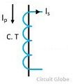 | 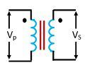 |
| Core | Usually built up with lamination of silicon steel. | It is made up of with high-quality steel operating at low flux densities |
| Primary Winding | It carries the current which is to be measured | It carries the voltage which is to be measured. |
| Secondary Winding | It is connected to the current winding of the instrument. | It is connected to the meter or instrument. |
| Connection | Connected in series with the instrument | Connected in parallel with the instrument. |
| Primary Circuit | Has a small number of turns | Has a large number of turns |
| Secondary Circuit | Has a large number of turns and cannot be an open circuit. | Has a small number of turns and can be an open circuit. |
| Range | 5A or 1A | 110v |
| Transformation Ratio | High | Low |
| Burden | Does not depends on the secondary burden | Depends on the secondary burden |
| Input | Constant current | Constant Voltage |
| Full line current | The primary winding consists of the full line current. | The primary winding consists of the full line voltage. |
| Types | Two types ( Wound and Closed Core ) | Two types (Electromagnetic and Capacitor voltage) |
| Impedance | Low | High |
| Applications | Measuring current and power, monitoring the power grid operation, for operating protective relay, | Measurement, power source, operating protective relay, |

No comments:
Post a Comment